Saturday 14 November 2015

RAPID PROTOTYPING - SILICONE RUBBER MOLD (SRM)


Silicone Rubber Molding  is a simple, accurate and forgiving process of making prototype parts. SRM is also the cheapest and fastest process to produce relatively small volume parts. The process start with a "Master Part" preparation. This part can be encapsulated with molding material and then many parts can be made from the resulting negative. This master can be encapsulated by supporting it on spacers and enclosing it in a retaining frame. The master part can be done using Fused Depositon Modeling (FDM) machine.

For an example,Trim Rear Pillar for a New Persona Car. The material to be used to do the master part is either PC or ABS. For my project, the material used to do the master part is ABS because PC material has been used up for other parts.  First of all, we do the parts at the Rapid Prototype by ourself because the vendor that has been appointed by us cannot do the parts. Time taken to finish the master part is approximately 131 hours or 6 days.


After the master part has been produced and taken out from FDM machine, it will come to the next process which is silicone rubber mold. An adjustable mold is placed around the master part and it should be no closer than 1 inch, so that the silicone rubber mold would be thick enough. The silicone rubber materials is mixed very well before pour it to make sure that air is not introduced into the material. When ready, pour the silicone rubber materials slowly to make sure no air pockets are left around the wall. Once the mold arrangement is filled, let it cure for 1 day before tear it apart.

Once the cure is finished, re-mold the arrangement. Since we made it one piece mold, cut it into two halves. One the cutting is completed, gently pull the two mold parts apart. Then, pull the master part out and now we have the mold, we can cast parts.
 

CONTROLLER AREA NETWORK (CAN) BASIC AND TECHNICAL OVERVIEW


 What is CAN?
CAN (Controller Area Network) is a multiplexed serial communication channel which is data/information are transferred among distributed to/from and electronic modules.
 
1. Why CAN?
        Widely Accepted Standard
·         "THE STANDARD" application in the automotive industry.
·         Gaining acceptance in the worldwide OEM.
 
        Robust
·         Handles extreme conditions well.
·         Simple to configure.
·         Good error detection capabilities.
·         Excellent two-wire fault tolerance capabilities:
Þ    Either of the two wires in the bus is broken.
Þ    Either of the two wires are shorted to power, to ground, or together.
        A Lots of software and hardware support available
·         Application layer and driver software available.
·         CAN Bus Analyzer/development tools.
·         CAN USER group conferences.
 Typical CAN application on vehicle are illustrated as below.


The structure of CAN are classify into CAN 2.0B and CAN 2.0A. Below specification may described the deferent between these 2 CAN protocol.

 
• CAN 2.0A (Standard Format)
- 11 bit message identifier
- Transmits and receives only standard format messages.


• CAN 2.0B (Extended Format)
- Capable of receiving CAN 2.0A messages.
- 29 bit message identifier. 11 bits for a CAN 2.0A message + 18 bits for CAN 2.0B message.


2.    CAN Bus Protocol
2.1 CAN Identifiers
Þ    Labels the content (type) of a message.
Þ    Performs acceptance test of messages.
Þ    Arbitrates & determines the priority of the messages. 

2.2 Arbitration

Carrier Sense, Multiple Access with Collision Detect (CSMA/CD)
·         Method used to arbitrate and determine the priority of messages.
·         Uses enhanced capability of non-destructive bitwise arbitration to provide collision resolution. 

2.3 Bitwise Arbitration

Any potential bus conflicts are resolved by bitwise arbitration
·         Dominant state (logic 0) has precedence over a recessive state (logic 1).


»        Competition for the bus is won by node 2 .
»        Nodes 0 and 1 automatically become receivers of the message
»        Nodes 0 and 1 will re-transmit their messages when the bus becomes available again. 
2.4 Bus Priority Concept
·         Each transmit buffer hold an 8-bit priority register.
·         Allows flexible priority schemes.
»        Fixed Priority for each buffer.
            »        Map a CAN ID to a priority.
»        First in, first out.
»        Back - to - Back transmission of same ID.
»        Situation priority. 
1.    CAN Error Detection
        CAN implements five error detection mechanisms.
                  ·         Three at the message level
»        Cyclic Redundancy Checks (CRC)
»        Frame Checks
»        Acknowledgment Error Checks
·         Two at the bit level
»        Bit Monitoring
»        Bit Stuffing 
2.    Requirement of CAN Controller
         Simple user interface to CPU
        Message filtering and buffering
        Protocol handling
        Physical layer interface 
3.    Summary of CAN Implementation
        Full CAN is not appropriate for Car Body for cost reasons:
Þ    The RAM required for message buffering and filtering is very silicon intensive and expensive
        A Full CAN receiver can have worst case Rx interrupt situations similar to Basic CAN receivers.
Þ    A FullCAN controller with less receive buffers than there are message identifiers experiences increased loading on the globally filtered Rx buffer
»        This is THE SAME situation as on a Basic CAN controller.


PROTON FIRST DEVELOPED ELECTRIC POWER STEERING

PROTON IRIZ has been successfully launched on Nov 2013 and together with the awesome look, PROTON IRIZ has been equipped with the latest technologies which could only be found mostly in luxury car.


Collaboration between PROTON and ZFLS Engineers has developed the first EPS for IRIZ, 18 months of hard work, from mechanical part design and fabrication, system and vehicle testing and software development has been conducted and checked thoroughly in order to provide the best EPS setup for IRIZ. 

WHAT IS EPS
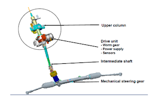
Electric Power Steering (EPS) is basically replacing the conventional hydraulic Power steering (HPS) with electronic actuated motor, sensor and also ECU. The EPS steering column diagram is as follows:  

   HOW EPS WORKS
The ECU will receive the torque and steering direction input and also at the same time receiving the vehicle and engine speed input from Engine Management System (EMS). The torque sensor will determine the load and direction, Motor will generate the rotating torque, the Intermediate shaft will deliver the amplified torque to the mechanical steering gear and later the steering gear will change the torque to the rack force.

There are few types of EPS developed specifically to cater different vehicle segments, for IRIZ, the engineers had opt for the Column type EPS whereby the drive unit consisting of ECU, motor & sensors  are basically located at the steering column, near to the steering wheels, this is the most suitable EPS configuration considering IRIZ compact, hatchback type vehicle which does not require more expensive type of EPS. The part cost is slightly cheaper but still able to provide good steering feel. Most of the A & B segment vehicles were actually using this type of configuration.

EPS VS HPS
The EPS motor draws power only when assists is needed, which means its consume less power compared to HPS whereby the driver pump will always turn.
The HPS also were actually using lots of mechanical components which subjected to wear and tear, there are multiple hoses routed within engine compartment whereby for the EPS, there are no hoses, only electrical connection which does not consume spaces.
In HPS also, it can only able to provide variable assist by using different flow control devices meanwhile for EPS it can be done by  simply tune the Software. In EPS also, since it does not involve fluid, thus there is no fluid to leak or dispose meanwhile for HPS, there will be an issue if there is any fluid leakage.

BENEFITS OF EPS
1. Fuel Efficiency, since it will only consume enegy only when steering
2. Reduce vehicle weight, the conventional hydraulic pump, oil reservoir, hoses and pipes valve will be remove, thus reducing the overall weight
3. Easy to assemble, No hoses to route, only few electrical connection
4. Easy to maintain, No steering oil, quick exam using diagnostic tool
5. Steering feel, stability & comfort, able to provide optimum assists force for different vehicle speed, excellent stability during high speed and also artificial R&H feel via software tuning


PROTON SAFETY - ELECTRONIC STABILITY CONTROL (ESC)

Have you ever experienced visiting PROTON showroom and the salesman seriously promotes PROTON car by talking about ESC? Have you heard about ESC? If you do not know what is ESC all about...., don't worry, below is a brief explanation about the system :-

What is Electronic Stability Control?
Electronic Stability Control (ESC) is a safety feature that detects and prevents (or recovers from) skids. ESC can help keep the driver from losing control of the car in a panic swerve (oversteer/understeer) or when driving on slippery roads.


How ESC works
ESC uses sensors in the car (wheel speed sensors, steering angle sensors and yaw rate sensors) to determine which direction the driver wants the car to go, and compares that to which way the car is actually going.
 
If the system senses that a skid is imminent or has already started -- in other words, that the car is not going in the direction the driver is telling it to go -- it can apply the brakes on individual wheels to bring the car back under control. Because the system can brake individual wheels, whereas the driver can only brake all four wheels at once. ESC can recover from skids that human driver cant. In many case engine throttle also is reduced.

Friday 13 November 2015

SHOULD WE STUDY MBA(EMBA)?


After have been working in Automotive industry for the past 20 years, specifically in product design in various area for 10 years and in project management team for the following 10 years, suddenly feel like to pursue study in non engineering field. I believe that the knowledge of engineering and operational must be blended together with account /financial, human resource, marketing etc. to make the work environment become more interesting. More important, any business decision to be made will be wisely based on the combination of technical and business factors.

Influenced by  UITM road show in July 2014 at SACC to promote Master and PhD program, I have decided to proceed my study  in UITM, Shah Alam.  In early September 2014, after complete the registration process and been given the student card, I re-started my "student life" in Executive Master In Business (EMBA). Felt little bit odd during the 1st class. I am the oldest student whereas the others are at the age ranging from middle of 20's to 30's.

after completion of 2 semesters and have studied subject like Organisation Behaviour, Human Resource, Accounting, Economics, Marketing etc, I start to realize how much the subjects have helped and improved my business acumen and to link it to the engineering matters. Ultimately, a wise decision is made to the interest of customers and hence to the company's business sustainability.

To the all executives, managers, bosses etc, I can guarantee you that MBA will help you to improve. Improve in managing people, business decision and to become a good leader instead of dedicated manager. Those who stay in Shah Alam......, UITM is the best place for you.....!!l